How to make a 3″ Exhaust / Muffler
From the time the mid-engine Spitfire was built, I always had this vision of making a better exhaust system. I liked the cobbled together system I had, but it did not look neat, and the diameter of the pipe was too small, apparently these 1.8T 20v engines need a minimum of 3” to reduce back pressure and allow the turbo to spool up faster.
So the exhaust project started…
First step was to draw it out and buy the parts, to my surprise just the raw bits to make the exhaust were really expensive, well over £300, just the 340 stainless steel sheet t make the silencer / muffler box was £63. Add on to that 3” and 2 ½” stainless tube, perforated tube for the baffles, flex, v bands, clamps etc, the price soon racked up.
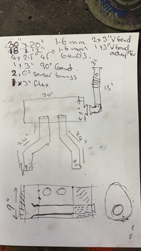
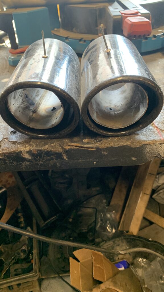
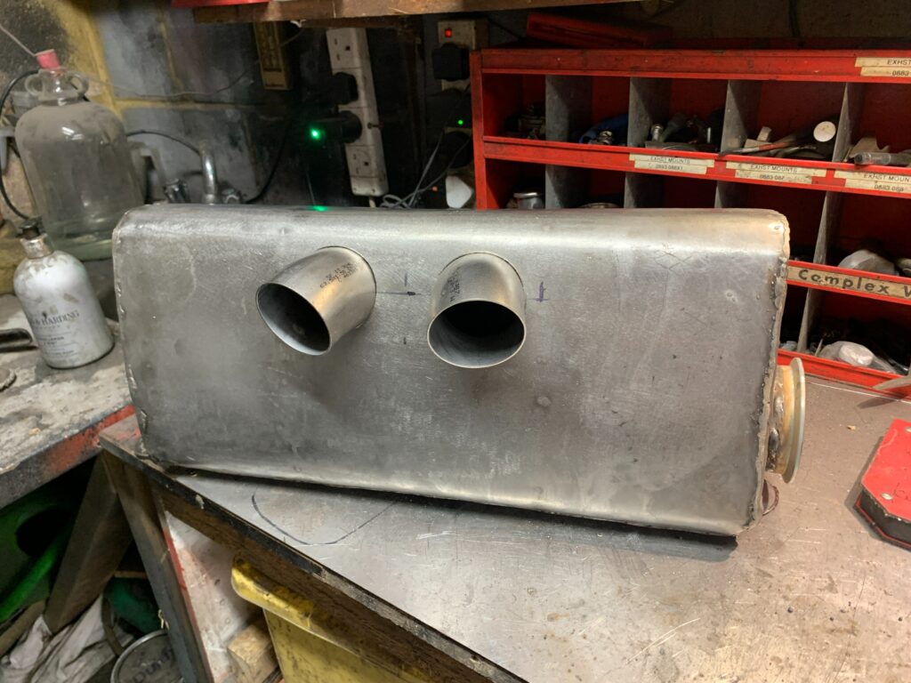
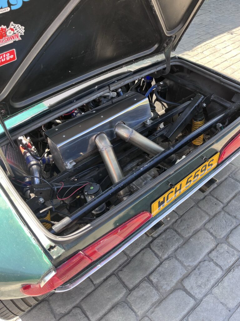
The aim was to make a box with an input on the end, and 2 x 2 1/2 “ exits in the middle of the box, so the tail pipes exit the car either side of the gearbox housing. I had been given two 4” carbon fibre exhaust tips for a bit of bling.
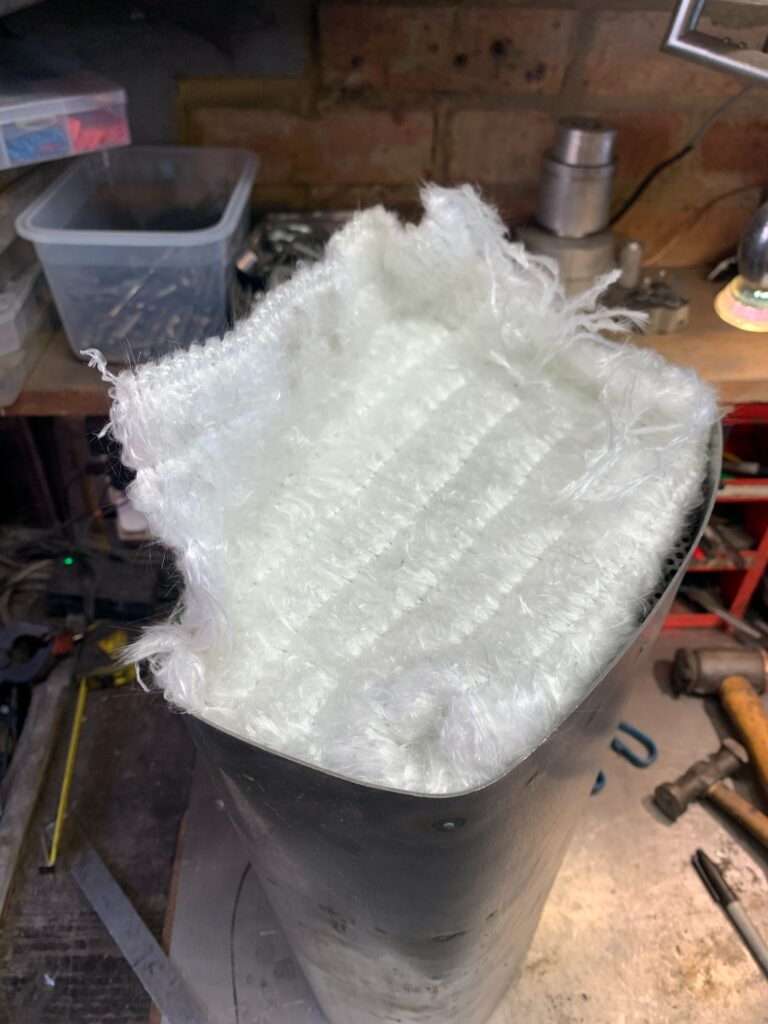
The exhaust box itself has 3 chambers, the first, on the exhaust inlet has a perforated tube running through that is wrapped with glass exhaust dampening, the exhaust then travels through the 2nd chamber in a solid pipe to the 3rd where it hits a wall of glass wool dampening, there is an open in that chamber’s wall to the 2nd, centre chamber where the 2 exit pipes are.
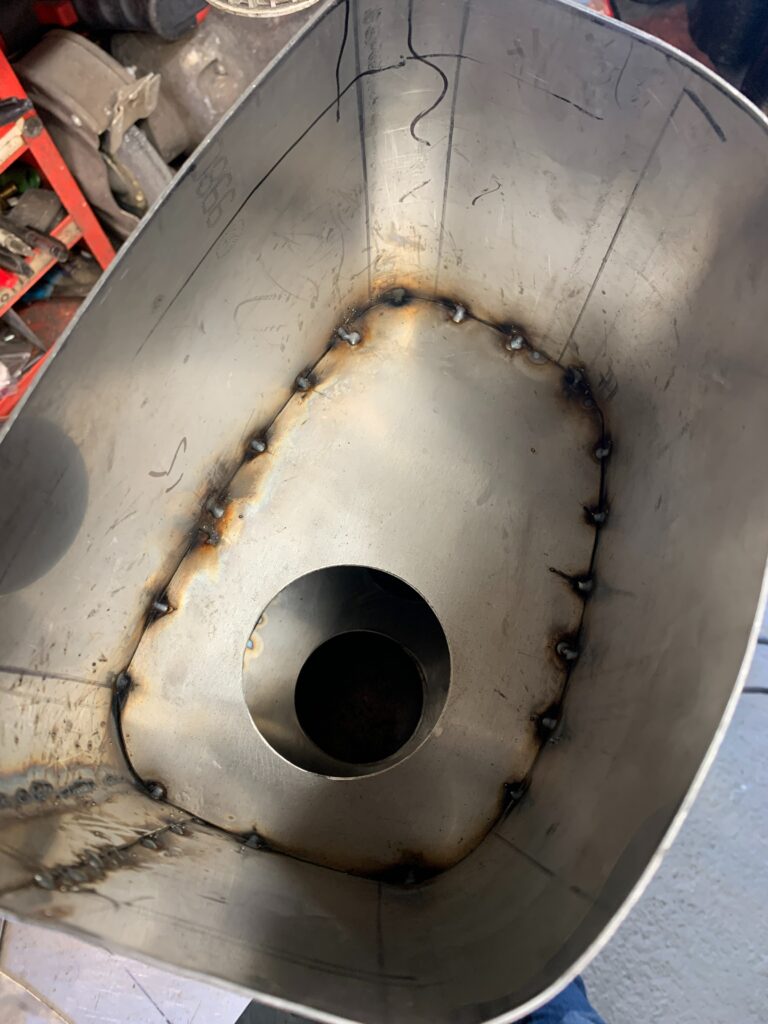
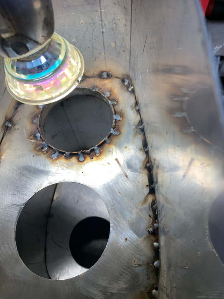
I was going to try and TIG weld the exhaust, but either my TIG is useless, or I just cannot TIG, I suspect it is the latter. So, I used stainless steel MIG using .8mm wire.
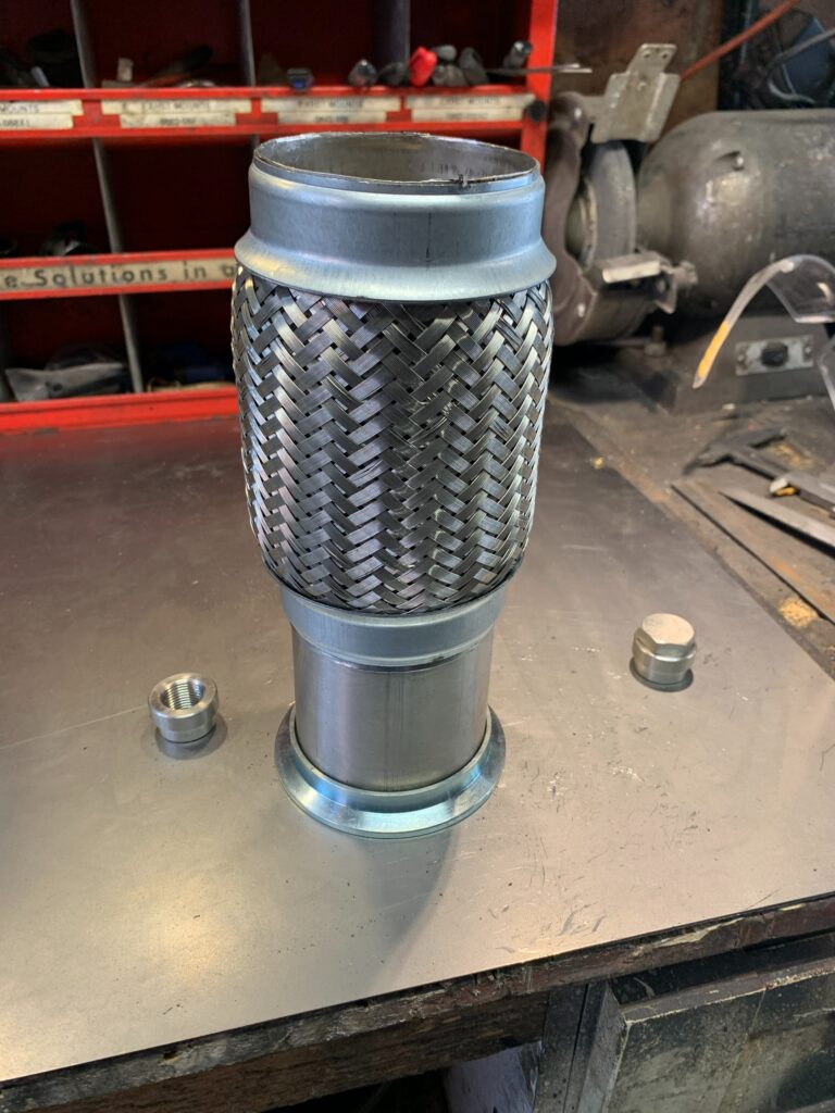
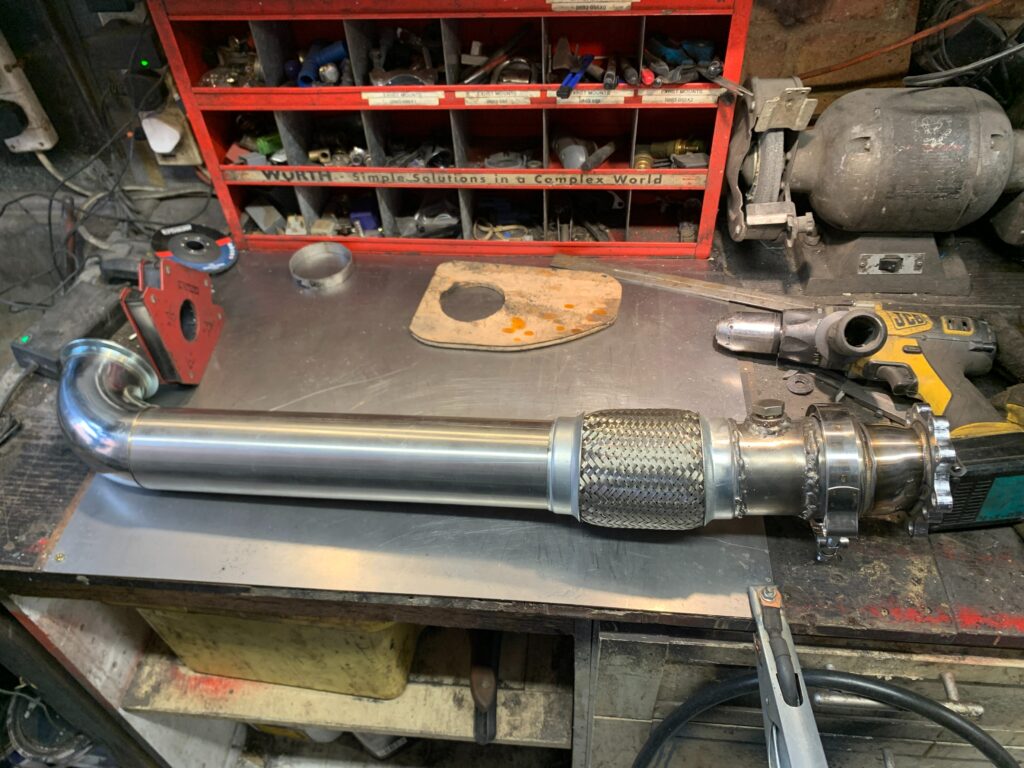
The downpipe from the turbo comprises of a V Band at the turbo, then a short 3” pipe with two O2 sensor bungs, one for the engine and one for a future gauge. Then there is a short flex, the through to another 3” V Band, then the muffler box.
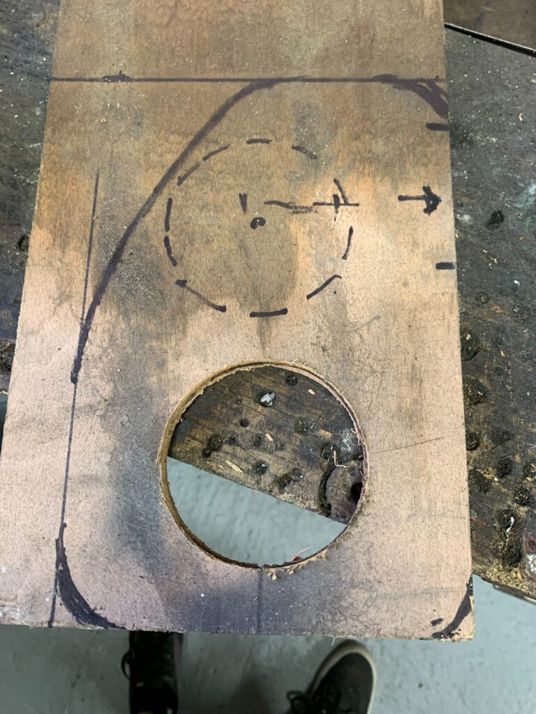
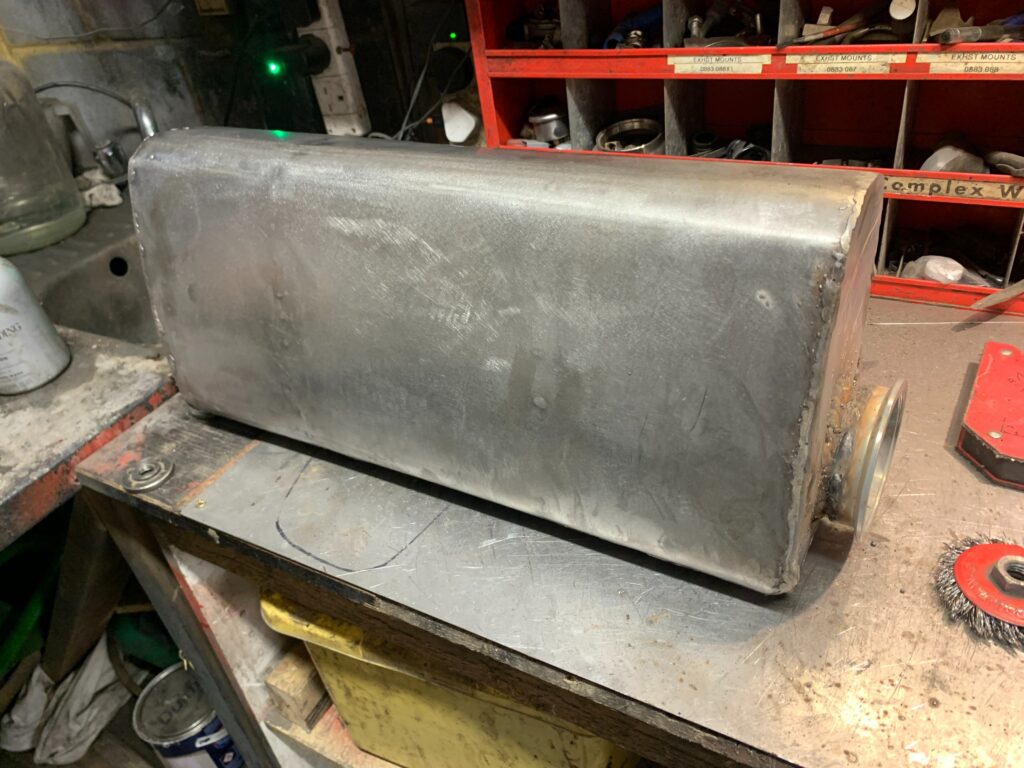
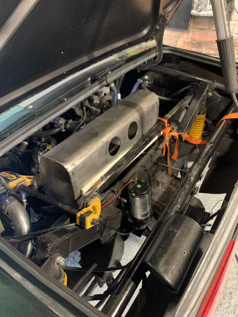
Constructing the box was a challenge, the stainless steel sheet was 1.2mm thick, I made a sheet steel roller, but that was no way man enough to roll the steel sheet to the desired shape. To help get the box the right shape I cut two wooden templates, my thought was to wrap the stainless round these templates to get the box shape, but again, the 1.2mm stainless is to hard to bend like that.
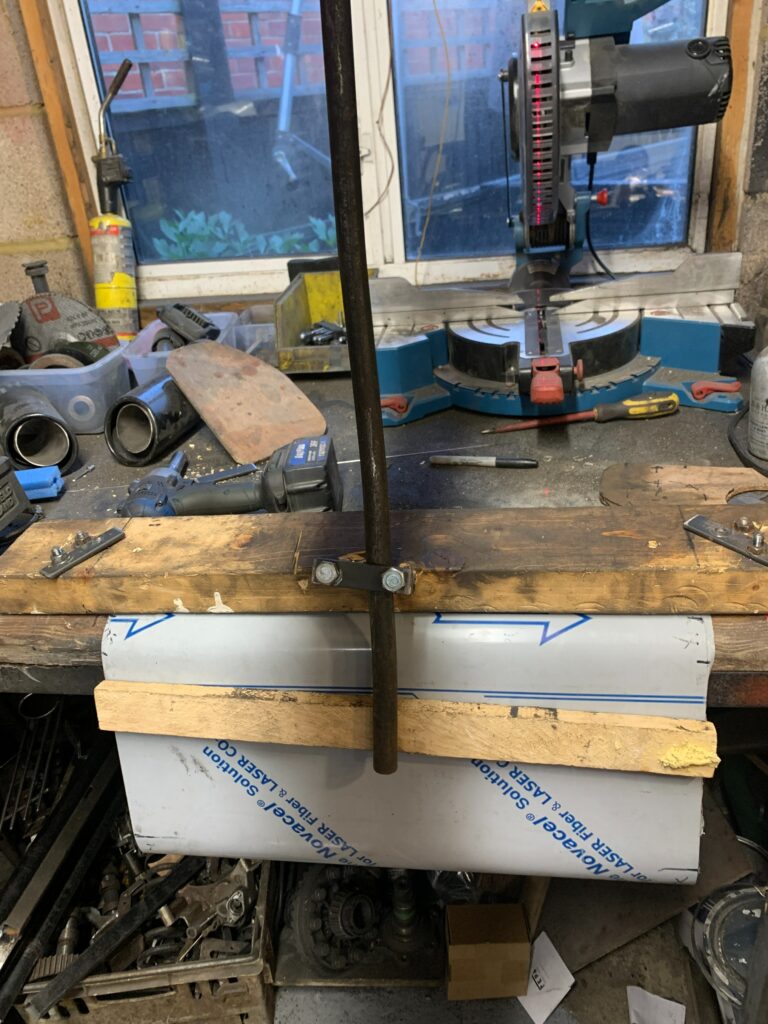
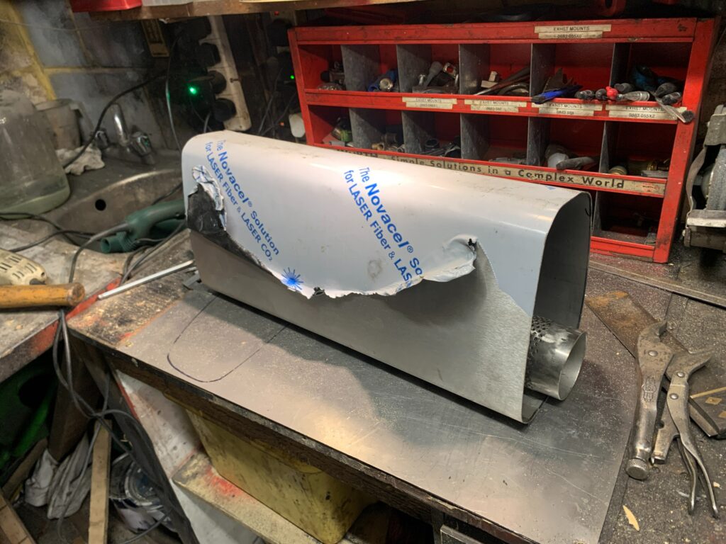
In the end I made a sheet steel bender on my workbench by clamping the sheet down, and using a long lever forcing the steel to bend over the edge of the bench, this approach worked out well. Then it was just a case of tack welding the seams of the box…
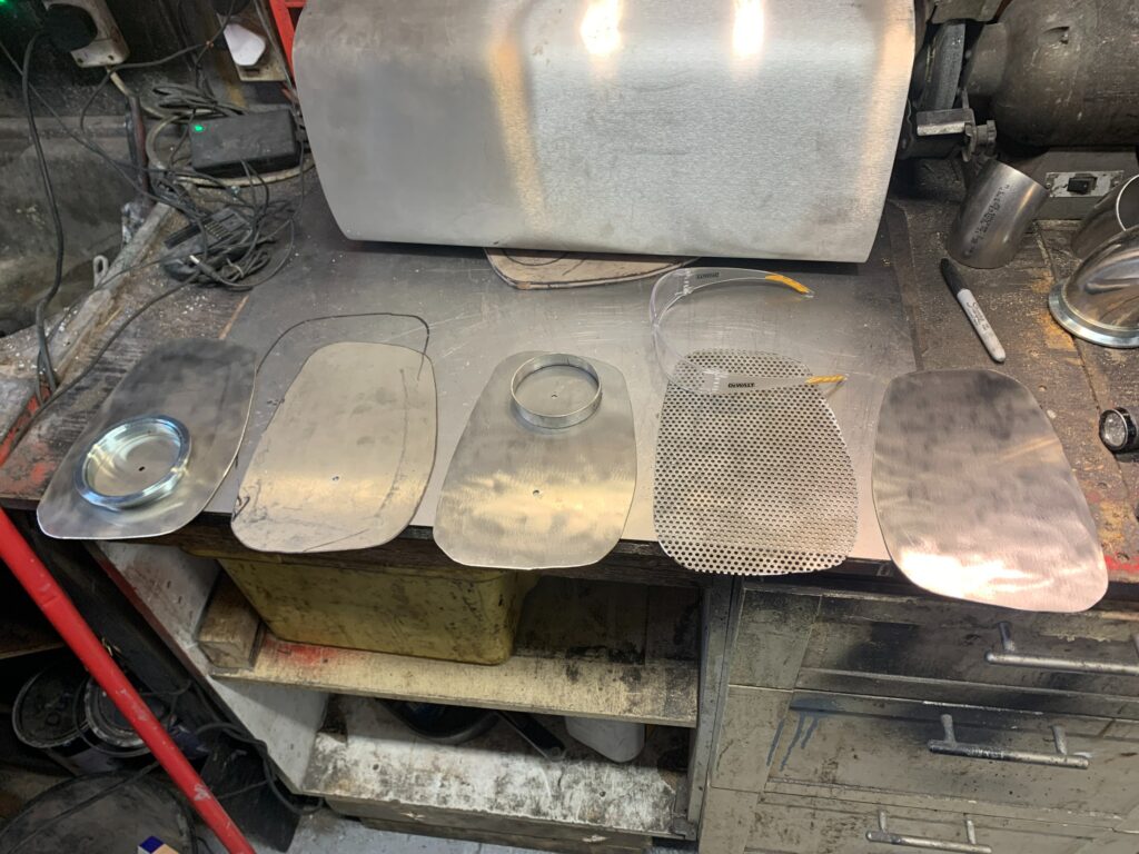
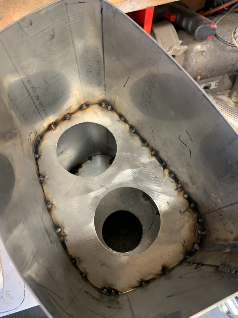
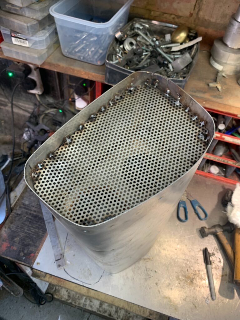
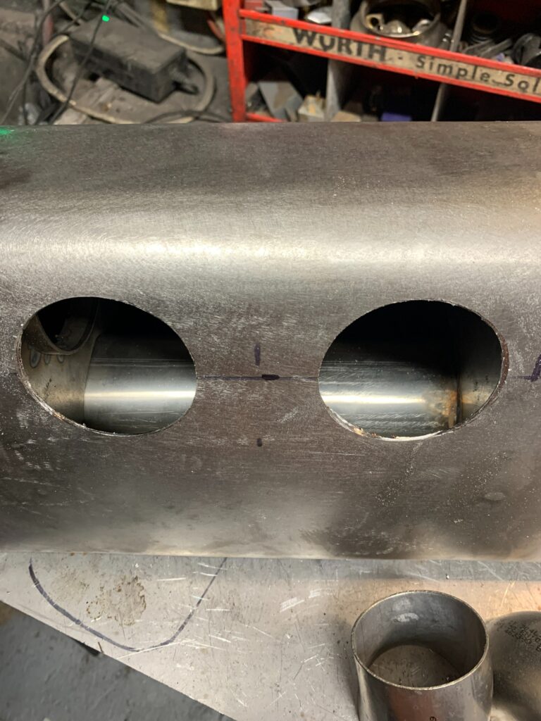
As the box has 3 compartments, I had to make 4 profile sections the same shape as the wooden templates I had made earlier. The first and 2nd has a 3” hole cut in them, the 3rd has 2 3” holes cut through, there was also a sheet of perforated steel for the last chamber (to hold the glass wadding in place)
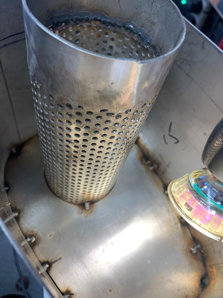
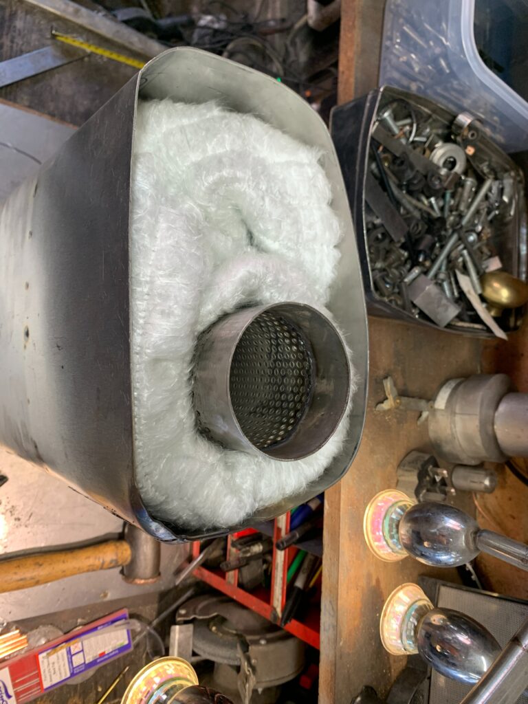
For the exhaust box through pipe, I started with a short section of solid 3” tube, that welded to the perforated tube, and that welded to a further sheet of solid tube. Then all ground down to form a seamless tube.
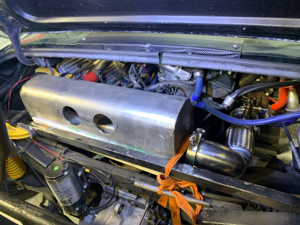
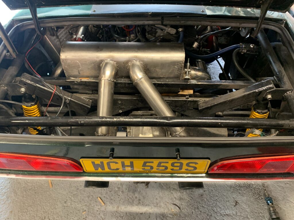
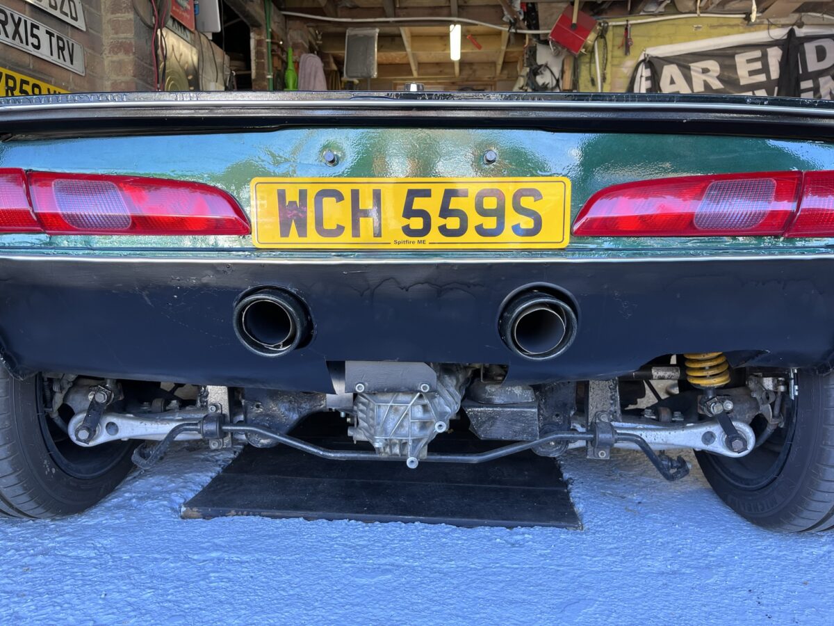
The final part of the exhaust was to cut two 4” holes in the car’s rear valance fir the tail pipes. Once cut, I slotted the tailpipes in the holes and made the connecting pipes from box to tips. A bracket joins the two tailpipes and a rubber mount secures them to the top of the gearbox’s gear selector bracket.
On the box itself, I have fitted a rubber mount either end.
Finally a polished stainless steel heatshield was made to cover the box with a 1/2” air gap.
I do have one issue, when the car stops, the heat soak from the box does make the heatshield quite hot, and as it is near to the boot/trunk lid I will have to find a way to keep it cool…