looks like a great project you have created for yourself, you are doing a great job with the detailed commentary, and pics, keep up the good work.
Have you just started this project ? , I ask because it seems as though things have progressed very quickly, or did you have the chassis made prior to deciding to go ahead, and you are simply modifying it to accommodate the jag engine ?
Either way its looks very promising, and cant wait to keep checking back for progress reports.
Good Luck !
Hi Kris I started 4 weeks ago (seems like a lot longer). My starting point was an idea to make a "Zonda spyder", an old jag engine and a pile of steel tube. I did some research on the web, found a blue print website, and website for the ultima GTR and parallel designs, and picked parts of their chassis for my topless number. Printed off tonnes of Zonda Images and scaled them up to get the right proportions.
Everything in the pictures is under a month old - My wife now wishes i had taken up golf, she thinks she might see more of me
Last night the Granada was taken away, so at least the front of the house doesn't look like a scrap yard. Cheers Nick
Karting
Silver Subscribed
Hi Nick That's amazing progress. If you go down the Holley route, make sure you use a good fuel filter, I had a holley in my MGB roadster v8 and i had a nightmare with the jets getting blocked, so much so i carried a rebuild kit with me in the car. [and i had to use it on the M2 hard shoulder on a trip to France, very scary. In the end i went the SU route, not as sexy but for me much more reliable. Keep up the good work. Grant
Nickt
Formula Junior
Silver Subscribed
Quote:
Originally Posted by
Hi Nick That's amazing progress. If you go down the Holley route, make sure you use a good fuel filter, I had a holley in my MGB roadster v8 and i had a nightmare with the jets getting blocked, so much so i carried a rebuild kit with me in the car. [and i had to use it on the M2 hard shoulder on a trip to France, very scary. In the end i went the SU route, not as sexy but for me much more reliable. Keep up the good work. Grant
Thanks Grant! Got the 1st wheel on to night, the rear passenger side one Interesting though thinking about the rear suspension... If I could use the original Scorpio front struts inboard like the do in the f430s and Zonda. If I lay them on top across the bell housing they seem to end up at the right point near the hub... As for the carbs I bought some (4) 175 cd Strombergs off a couple rover 3.5 V8, I was pondering whether i could do what the mad biker did with his V12 jag and stick two Peugeot diesel turbos on it and use these carbs? Should be OK for 400 bhp? http://www.visordown.com/motorcyclenews/view/v12_drag_bike_for_sale_on_ebay/1564.html
I am also thinking of using the Megasquirt V3 direct ignition ECU - but I have to sweet talk the missus for that ;-)
F1 Rookie
Consultant
Quote:
Originally Posted by Nickt
Thanks Grant! Got the 1st wheel on to night, the rear passenger side one Interesting though thinking about the rear suspension... If I could use the original Scorpio front struts inboard like the do in the f430s and Zonda. If I lay them on top across the bellhousing they seem to end up at the right point near the hub... As for the carbs I bought some (4) 175 cd Strombergs off a couple rover 3.5 V8, I was pondering whether i could do what the mad biker did with his V12 jag and stick two Peugeot diesel turbos on it and use these carbs? Should be OK for 400 bhp? http://www.visordown.com/motorcyclenews/view/v12_drag_bike_for_sale_on_ebay/1564.html
I am also thinkiing of using the Megasquirt V3 direct ignition ECU - but I have to sweet talk the missus for that ;-)
Those Strombergs are similar to what the Etypes and early XJ12s came with, nothing to brag about. If you find some big SUs you will get somewhere, not quite like a Weber setup but a big improvement over those Strombergs.
Nickt
Formula Junior
Silver Subscribed
Quote:
Originally Posted by
Those Strombergs are similar to what the Etypes and early XJ12s came with, nothing to brag about. If you find some big SUs you will get somewhere, not quite like a Weber setup but a big improvement over those Strombergs.
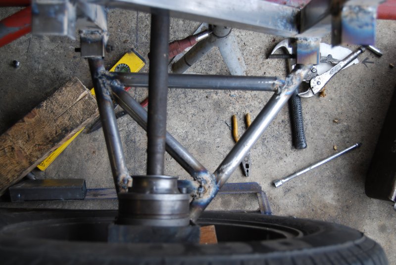
I would love to go the weber route, but at that cost it would be easier and cheaper to go modern ECU injection. Here are some pictures from tonight, as you can see the chassis is now a fetching shade of red oxide - nice! The picture of the front hub shows the "plug" and transit trackrod end the lower plate is a Cortina balljoint. I have run out of MIG wire so had to call it a day. I like the picture of the back of the car, kind of looks right
Nickt
Formula Junior
Silver Subscribed
OK, its not a good picture but would this work? If I took the front Macpherson struts and mounted them as in the picture. I would have to modify the struts to fit a bush at the top instead of the 3 bolt plate but - is it a goer?
F1 Rookie
Consultant
What about spring rates? Will the struts even work horizontally? With double wishbones why not do dual coil-overs.
Nickt
Formula Junior
Silver Subscribed
J
Quote:
Originally Posted by
What about spring rates? Will the struts even work horizontally? With double wishbones why not do dual coil-overs.
Yes, I have looked at this type of setup on the GT40 website. Just trying to think of way to recycle as much of the donor as possible. I also wanted to keep the design as close to the C12 as possible. The springs should be OK, they kept an iron 2.9 V6 from scraping on the tarmac. I guess the only way to be really sure is to weigh each corner and see what springs I need?
Karting
Not Subscribed
Quote:
Originally Posted by Nickt
OK, its not a good picture but would this work? If I took the front Macpherson struts and mounted them as in the picture. I would have to modify the struts to fit a bush at the top instead of the 3 bolt plate but - is it a goer?
Nick,
Just looking at the picture I would say you will not have enough movement of the shock to provide effective damping. Move the bottom of the shock in towards the pivot and on a 90 degree arm.
Regards Trevor.
Karting
Not Subscribed
Join Date: Feb 2007
Location: UK
Full Name: Kris
Posts: 106
Quote:
Originally Posted by Nickt
Hi Kris I started 4 weeks ago (seems like a lot longer). My starting point was an idea to make a "Zonda spyder", an old jag engine and a pile of steel tube. I did some research on the web, found a blue print website, and website for the ultima GTR and parrallel designs, and picked parts of their chassis for my topless number. Printed off tonnes of Zonda Images and scaled them up to get the right proportions.
I am impressed by the amount you have achieved in such a short time, from planning to basic layout in a month, faster than any Italian car manufacturer i know.
Quote:
Everything in the pictures is under a month old - My wife now wishes i had taken up golf, she thinks she might see more of me
Well if you can throw yourself at this and achieve what you have done in a month, I think you would be a pro golfer within 3 months.
Quote:
Last night the Granada was taken away, so at least the front of the house doesn't look like a scrap yard. Cheers Nick
Well at least you can now go around and welcome the new neighbours to the neighbourhood. lol
Karting
Not Subscribed
Join Date: Sep 2004
Posts: 77
Quote:
Originally Posted by
Nick,
Just looking at the picture I would say you will not have enough movement of the shock to provide effective damping. Move the bottom of the shock in towards the pivot and on a 90 degree arm.
Regards Trevor.
I am enjoying your fantastic project, keep up the good work.
I have a couple of thoughts (hopefully helpful) based on structural engineering, I hope any mechanical engineers out there will please jump in and correct some of my base assumptions...
To explain myself better I need to draw some sketches and write plenty more, but given the fanastic speed you are working at, I reckon I'd better speak now, because you'll have built it by tomorrow!
So to the points: 1) a stated by Trevor, the coil over shock units will have quite a short throw and so the dampers may not be effective. 2) If the dampers are oil filled, then having them flat (or near flat) might not be ideal
HOWEVER 3) what I am really concerned about is the stress level on the inclined strut. Just applying structural principles of "resolving the forces"... the force in the strut is:
F = W / cos A
where F = force in strut (and connection welds) W= corner weight of car that that strut is attached to... (MUST be multiplied by a factor of safety to allow for bump shock...) A = angle from the vertical.
Say your corner weight is... car 800Kg, with 40% front 60% rear split, divided between two wheels = 170Kg factor of safety for bump say x3 (MIN) = 510Kg design load per wheel/suspension strut (peak).
now apply formula A = 0 (ie: strut vertical and above wheel) Force in strut = 510Kg A = 10 degrees from vert Force = 518Kg
The wider the angle between the direction of the force and the restraining strut... the less effective that strut is. To provide enough vertical force, more and more force is induced in the strut and its connections. I would NOT recommend the connection detail you are suggesting as the forces would be amplified badly, as the struts are too flat.
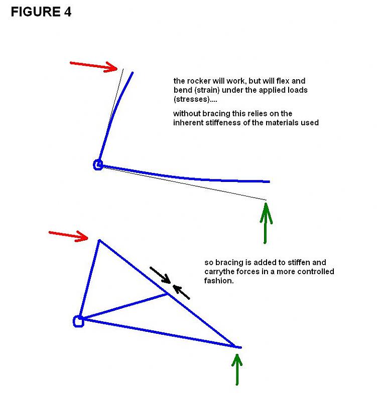
The horizontal strut set ups you will have seen on race and supercars look similar to your sketch, but are subtly different to avoid this problem... SEE SKETCHES ATTACHED
Use of a push rod and load rocker controls how the forces are moved around and are much more effective. There is still amplification of the forces, but in a lesser degree.
HAVING SAID THE ABOVE, your car will be very light so with a few sums and some very good welds your own arrangement is theoretical workable. But I fear you are adding the some very highly stressed connections to components you REALLY DO NOT want to come undone!
Better to look for another idea... say a traditional inclined coil over from the lower wishbone, mounted within the wishbones?
Yours,
David
Nickt
Formula Junior
Silver Subscribed
Join Date: Feb 2006
Location: Richings Park, Iver
Full Name: Nick T
Posts: 998
Quote:
Originally Posted by
I am enjoying your fantastic project, keep up the good work.
<SNIP>
Yours,
David
Wow, If I had doubts and i did, you have helped make my mind up The oil filled struts would need replacing with gas ones, and although i love the look of the "in board" suspension I can't justify the costs. If your sums are right, and I have no reason to disbelieve them, how do other cars like the Zonda manage using the 2nd picture in your sketch? The attached 3 C12 photos clearly show the damper attached to a bracket on the top wishbone. Cheers Nick
Actually thinking about it more, if the triangle was 1:1 with the wishbone, and the damper inclined in board, I could maintain the minimum 45 degrees needed for oil filled struts?
Karting
Not Subscribed
Join Date: Sep 2004
Posts: 77
Quote:
Originally Posted by Nickt
Wow, If I had doubts and i did, you have helped make my mind up The oil filled struts would need replacing with gas ones, and although i love the look of the "in board" suspension I can't justify the costs. If your sums are right, and I have no reason to disbelieve them, how do other cars like the Zonda manage using the 2nd picture in your sketch? The attached 3 C12 photos clearly show the damper attached to a bracket on the top wishbone. Cheers Nick
Okay, I know what I want to explain, but I'm not sure how best to do it... There are a lot of effects at play here, load, leverage, resolving of forces.
If you want to understand your design, you have to be able to break it down in your mind and look at parts of the design in isolation, really think about where the forces come from, in what direction and how that will be countered.
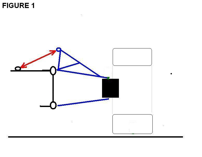
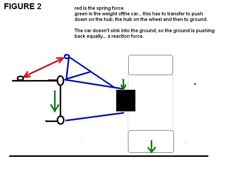
FIGURE 1: my awful drawing of ZONDA suspension. FIGURE 2: I have added some arrows to indicate load FIGURE 3: here it gets messy... read the notes and move onto my next post...
DKHudson
Karting
Not Subscribed
Join Date: Sep 2004
Posts: 77
Quote:
Originally Posted by
FIGURE 3: here it gets messy... read the notes and move onto my next post...
So why does this work, but I say your version doesn't? Strictly speaking your version would work (theoretically), but it would transfer the forces differently and be inefficient and very highly stressed. So it is not a good solution.
Back to forces...
FIGURE 5: We need to look at direction of forces...
While the Zonda and others use a rocker (modified top wishbone) to press directly down vertically at the connection to the hub, transfer the forces through that rocker and then into a road spring... your proposed design attached a road spring as a steep angle to press (more or less) back against the hub. Because the spring is so flat it would generate little down force in comparison with the force in the spring, but significant sideways forces. Hence the connection would be highly stressed.
I hope I have explained this clearly. Really I'd rather draw loads and loads of diagrams, but I don't have a scanner at home so that isn't an option. If I am not making sense please ask questions and I try to clarify.
DISCLAIMER: In this modern world I must cover myself... I am not a engineer specialising in automotive design, I am merely discussing basic structural principles that could be applied in order to understand some of the issues. This is not a full or detailed explanation of the engineering design. I have not checked or analysised any part of your proposed design and can not take any responsibility for this.
Yours,
David
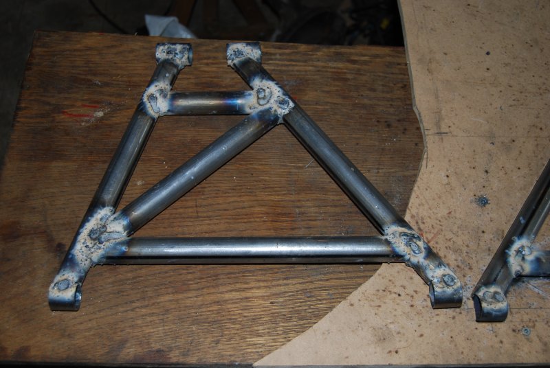
PS: I'm glad to see some diagonal bracing (triangulation) being added to your chassis... always a good thing.
Nickt
Formula Junior
Silver Subscribed
Posts: 998
Hi David, Do you know how you work out what length/strength road springs you need? I am using a set of Koni 8212s (as kindly donated by a lovely fchat subscriber!)
As for the suspension I am going to use a conventional setup, and copy that of my 308 GT4. In order to get the same wheel track as the Zonda my chassis requires the wishbones to be exactly the same size as the Ferrari! (30cm between chassis and hub)
Yesterday I finished one rear hub, started the other and fabricated and welded the wishbone pick up points to the rear end.
If any one wants to donate some road springs, a pedal box or the use of a TIG welder I would be eternally grateful
I am also after a pair of Peugeot diesel turbos
Also if anyone wants to come round and offer advice that is welcome too!
Kind regards Nick
Karting
Not Subscribed
Join Date: Sep 2004
Posts: 77
Quote:
Originally Posted by Nickt
Hi David, Do you know how you work out what length/strength road springs you need? I am using a set of Koni 8212s (as kindly donated by a lovely fchat subscriber!).....
Nick
No, not really. My engineering knowledge is more structural than mechanical. However I'll have a guess:
Once you have a feel for you finished vehicle weight you (we) could then have a go at working out the corner weights, from that a few sums would give the basic spring forces needed to support the car.
The spring length (laden) is going to have be governed by the shock absorbers your have there. ie: the spring (LOADED) will have to be the distance btween the spring pans with the strut say 1/2 extended and the adjustable pan at 1/2 range. From there you'll have to work back to get the length of the unladen spring.
SPRING LENGTH (laden) = [ UNLADEN LENGTH - (rate x load) ]
turn the formula around
UNLADEN LENGTH = [ SPRING LENGTH LADEN + (rate x load) ]
(Check that the UNLADEN LENGTH is greater than the fully extended length of the damper... otherwise the spring will go slack and mis-seat every time you go over a jump!)
rate in mm/Kg, or mm/KN (KiloNewton), inches/lb - depending on the units used... load expressed in same unit ...so if you get springs rated in inches/lb you will have to work out your loads in lbs (or convert Kg into lbs...)
That will get the car sitting roughly at the correct right height (fine tuning done by adjusting the adjustable spring pan). UNFORTUANTELY this is where my engineering knowledge starts to run out. The rate of the spring you choose will govern how hard the suspension feels. I can not really advise on what those rates should be in numbers, I fear trial and error may be required.
Given that your car is for road use and is very light... you'll want the rear (heavy end) no more than moderately stiff, but the front may actually have to be suprisingly soft, so that you get the suspension to follow the road surface and not skip. Stiff is okay on a race track, but roads are full of bumps and dips and over hard suspension becomes less effective, as the tyres skip and jump.
For my little Fiat X1/9 the front springs were shortened, but were still quite soft, the damping was set correspondingly soft, tyre pressure were low 18psi and it worked really well! Because the nose was so light (NOTE: x1/9 = 880Kg kerb weight - maybe something similar to your special?)
OKAY I HAVEN'T DONE THIS BEFORE, but I'll have a GUESS... say we want 4" (100mm) suspension travel on bump say at 2G (2 x gravity vertical acceleration)
say 800Kg, 40/60% split >> rear 60% x 800 = 480Kg
so each rear corner 240Kg (standing still) look at a 2G bump, 2 x 240Kg and the corner load at 100mm travel is 840Kg
STANDING CAR = 240Kg
load in spring (vert effect) = 240 * 300mm / 200mm = 360Kg (vert) = W
Spring is lying at and angle of 40degree off vert so F = W / cos A = 360 / cos(40) = 762Kg
Hence the spring needs to generate 762Kg at its standing laden length...
PEAK LOAD
Wpeak = 480Kg * 300mm / 200mm = 720Kg
Fpeak = 760 / cos(40) = 1524Kg
Hence the spring needs to generate 1542Kg at the bump spring length (fully closed)...
SUSPENSION travel = 100mm to bump (closed) at the wheel.
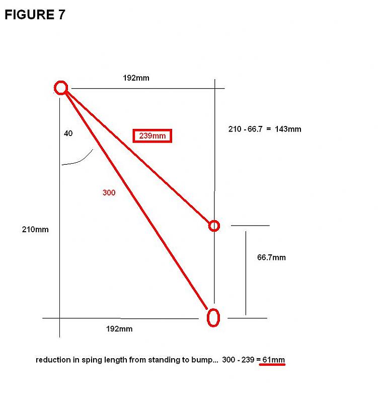
Spring closes 61mm from standing to bump (peak load) (SEE FIGURE 7 - actually I'd have to go further into the geometry as the end of the spring strut would travel on an arc - but this is near enough for a guess)
SO back to earlier formula... UNLADEN LENGTH = [ SPRING LENGTH LADEN + (rate x load) ]
If strut standing is 300mm between spring pans (assumption)
UNLADEN LENGTH = 300 + (0.21 x 762) = 461mm
So based on all the above guess work you need a 460mm spring rated to 0.21mm/Kg of the REAR SUSPENSION. The front would need another calculation.
BUT THIS IS A GUESSTIMATE, NOT ACCURATE... we would have to work with real figures to get a starting point... then I'd stress we are talking a starting point! I reckon you'll still need to try a couple of sets of springs to get the thing to feel right.
ASSUMPTIONS MADE (ie: engineering guesses!): 1) weight of car 800Kg 2) weight distribution 40/60 3) geometry of rear suspension (length of wishbone, angle of strut, connection point of strut) 4) geometry of strut, open, standing and closed length 5) required suspension travel.
ANYHOW - I hope I have showed roughly how we could go about roughing out the spring rate. Frankly trial and error might be just as quick!
DISCLAIMER: the above calculation is an EXAMPLE ONLY and does not represent real data and can not be applied to any particular car. This is for discussion purposes only. I am not a mechanical engineer, I am merely discussing engineering principles tha might be applicable for this subject.
Yours,
David
Nickt
Formula Junior
Silver Subscribed
Rear lower Wishbones
I Have now nearly made the lower rear wishbones. I made an MDF jig to ensure that both sides are identical. Just a touch more on one side to do and they are done. The top ones will be fully adjustable for camber etc..
Karting
Not Subscribed
Join Date: Sep 2004
Posts: 77
Quote:
Originally Posted by Nickt
Hi David, Do you know how you work out what length/strength road springs you need?......
Also if anyone wants to come round and offer advice that is welcome too!
Kind regards Nick
OKAY anybody fancy a SILLY practical experiment? I am used to dealing with beams and steel, but normally on retaining walls and other things that do not move. Cars do move and so are subjected to dynamic forces which I am not quite sure how to quantify.
We therefore need a silly two man experiment.
EQUIPMENT 1 x car (any type) 1 x driver 1 x passenger observer 1 x kitchen scale (preferably good quality digital or dial type) 1 x 1kg weight (eg: bag of sugar)
METHOD 1) Secure the bag of sugar to the scale (bluetack?) and place the scale level on the floor in the car. 2) Check the measured starting weight of the test weight (bag of sugar) 3) The driver now needs to find one of those big dips/bumps in the road that is covered in scratches, where other people have bottomed out their cars. 4) Make a few passes to establish the maximum safe speed to take this bump without actually breaking the car, but it still wants to be enough to really sit it hard down on its suspension. 5) Make the measurement runs and read the peak weights for the 1Kg bag of sugar. 6) Stop the car and recheck the basic weight of the test load.
Assuming you have a 1Kg test load, if the peak weight seen is 2Kg then the car has just pulled a 1G vertical acceleration (ie: 2G - 1G static gravity). (Everything is subjected to 1G anyhow due to gravity). Likewise 1.5Kg is 0.5G...
Now for the tricky bit, put the scales and sugar back in the kitchen without getting caught!
This would actually be useful as it will give a feel for the range of forces NickT's road springs will be subjected to AND the forces the chassis, suspension and all things will be subjected to. If (for example) a big road bump doubles the weight of a bag of sugar, it will do the same to 400Kg of Jaguar V12... double it effectively to PEAK load 800Kg.
Oh and if anybody actually knows the answer of the assumed design G forces that a production car should be able to handle, please speak now and save a lot of messing about. Thank you.
While we're at it... any Nissan Skyline owners out there? What's the biggest lateral and braking G forces you've recorded on your dashboard Xbox computer thingy? (preferably not induced by hitting something solid...)
Answers on a post card...to I CAN'T BELIEVE I JUST DID THAT WE'RE JUST BIG KIDS INTERNATIONAL
This is how science moves forward. Silly experiments!